The paver walking system is mainly composed of a walking computer, two walking pumps, two traveling motors, a crawler traveling mechanism and a rotational speed sensor. Among them, the walking computer keeps the walking speed of the paver constant, thereby meeting the construction requirements. . In order to find the cause of the fault, we perform the following fault diagnosis according to the structure and working principle of the walking system.
(1) Release the brake. First, push the black knob of the two-position four-way valve acting as the brake on the transfer Case and turn it clockwise to make the paver in the initial operation state. At this time, the pressure oil of the right travel pump reaches the brake cylinder and opens the brake. The brake of the machine was released, and the following phenomenon occurred: the left crawler did not move, the right crawler moved forward quickly, and the machine turned sharply to the left. This phenomenon indicates that the fault is not caused by the brake system.
(2) Apply emergency measures. Pull the emergency transfer switch S70 behind the power distribution box of the main control console to the up position, so that the machine is in the initial operation state. The following phenomenon occurs: the left crawler moves forward slowly, and the right crawler moves forward quickly, resulting in leftward Sharp turn, the fault could not be lifted. This shows that the fault is not caused by the walking computer.
(3) Replace the plug of the left and right travel pump solenoid valve coils so that the machine is in the initial operating state. At this point, the left track does not move, and the right track is swiftly moving forward, causing the machine to make a sharp turn to the left.
(4) Unplug the right travel pump solenoid valve coil to keep the machine in the initial operating state. At this point, the left track does not move, the right track moves forward quickly, causing the machine to make a sharp turn to the left; the switch S70 is pulled to the up position and the machine is in the initial operating state, and the left track is slowly moving forward, the right track Going forward quickly, causing the machine to make a sharp turn to the left.
(5) Unplug the left travel pump solenoid valve coil to make the machine in the initial operation state. As a result, the left track does not move, and the right track moves forward rapidly, causing the machine to make a sharp turn to the left; the switch S70 is pulled to the up position. The machine is in the initial operating state. At this time, the left track does not move, and the right track moves forward rapidly, causing the machine to make a sharp turn to the left.
The above situation indicates that the machine failure may be caused by the right travel pump, that is, the right travel pump always has a large flow output in one direction (forward direction).
When the switch S70 is in the normal position (ie, pulled to the down position) and the machine is in the initial operation state, the left travel pump has no flow output due to the protection function of the walking computer, but the right travel pump always has a large flow output in one direction. , so that the machine makes a sharp turn to the left; when using emergency measures (switch S70 is pulled to the up position) and the machine is in the initial operating state, since the left and right travel pumps are not controlled by the walking computer, the left travel pump has a smaller flow rate. The output makes the left track slowly move forward, but the output of the right-flowing pump in one direction also causes the machine to turn left.
(6) In order to further verify the correctness of the fault judgment, we performed the following operations:
When the emergency switch is placed in the normal position (switch S70 is pulled to the down position), start the engine and adjust the throttle to the rated speed. The toggle switch S6 is placed in the working position, the steering potentiometer is centered, and the speed potentiometer is set. 2m/min, push the joystick to the retracted position, press to release the emergency stop button. At this time, the left crawler does not move, the right crawler moves forward quickly, and the machine makes a sharp turn to the left; use emergency measures (switch S70 pulls up) Position), and perform the above-mentioned retreat operation, at this time, the left crawler belt slowly retreats, the right crawler belt moves forward quickly, and the machine makes a sharp turn to the left.
This verification further illustrates that the right travel pump swashplate is always in the output position of a large flow in one direction (forward direction).
The possible cause of the right-hand drive pump swashplate being in the unidirectional high-flow output position is that there is a problem with the solenoid valve (if it is not a problem with the valve, only the entire right-going pump is removed to the test rig for inspection). Therefore, we removed the right-hand pump solenoid valve, installed it after cleaning, and the fault was eliminated when the machine was tested.
Our company absorbs advanced technology and experience from home and abroad, and strictly according to the requirements of GMP, we design, develop, produce, install and serve the products, ensuring the quality of products.In the development and research of drying equipment, we constantly innovate and transform, and design and manufacture a series of advanced and energy-saving products.And according to the needs of the market research and development of the forty kinds of drying, granulating, mixing, dust series, products are widely used in pharmaceutical, chemical, foodstuff, light industry and other industry industrial drying dehumidifying raw materials or products, well received by users.Welcome customer materials test and inspection.
Our company is located in the beautiful scenery of jiangnan, the industrial star city of changzhou, located in the hinterland of Shanghai and ning economic development zone, the climate is pleasant, the traffic is convenient.The company has strong technical force, perfect test system, sophisticated processing equipment and strict management system
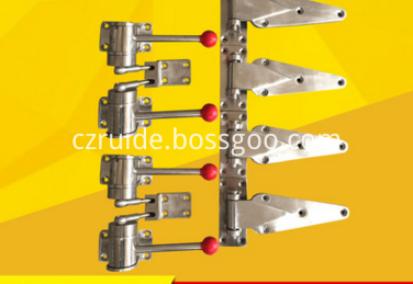
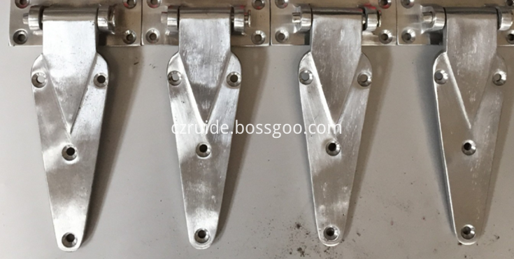
Door Lock Door Hinge Drying Equipment Accessories are used for the Drying Oven Machine ,materials is stainless steel


China leading manufacturers and suppliers of Door Lock Drying Equipment Accessories, and we are specialize in Door Lock Accessories , Door Hinge Drying Equipment Accessories, Drying Equipment Accessories, etc.
Door Lock Drying Equipment Accessories,Door Hinge Drying Equipment Accessories,Drying Equipment Accessories,Door Lock Accessories
Door Lock Door Hinge Drying Equipment Accessories
Door Lock Drying Equipment Accessories,Door Hinge Drying Equipment Accessories,Drying Equipment Accessories,Door Lock Accessories
Changzhou Ruide Drying Engineering Technology Co., Ltd , https://www.rddryer.com