First, the repair method to find the fault should be outside the first, after the first easy, difficult to zero, a key breakthrough. The method can be roughly divided into the following types:
1. The sensory method uses the senses to directly determine the cause of the malfunction. Through the appearance inspection, it can be found such as disconnection, desoldering, wiring short circuit, fuse tube broken, burned components, mechanical damage, copper foil on the printed circuit Starting and breaking, etc.; the temperature rise of the battery, resistor, transistor, and integrated block can be touched. The cause of abnormal temperature rise can be found by referring to the circuit diagram. In addition, the hand can also check whether the components are loose, whether the integrated circuit leg is firmly inserted, whether the switch is stuck; you can hear and smell the sound and smell.
2. Measure voltage method to measure whether the working voltage of each key point is normal, and find the fault point relatively quickly. Such as measuring A / D converter operating voltage, reference voltage and so on.
3. Short-circuit method In the above-mentioned inspection A/D converter method, a short-circuit method is generally used. This method is used more often when repairing a weak current and a micro-electric apparatus.
4. The open circuit method disconnects the suspicious part from the entire unit or unit circuit. If the fault disappears, it indicates that the fault is in the open circuit. This method is mainly suitable for short circuits in the circuit.
5. Measuring component method When the fault has been reduced to a certain place or several components, it can be measured online or offline. If necessary, replace it with a good component. If the fault disappears, it means that the component is broken.
6. The interference method uses human induced voltage as an interference signal to observe the change of the liquid crystal display and is often used to check whether the input circuit and the display part are intact.
Second, repair techniques For a fault instrument should first check and determine the fault phenomenon is common (all functions can not be measured), or personality (individual function or individual range), and then distinguish the situation, symptomatic solution.
1. If all files cannot work, check the power supply circuit and A/D converter circuit. When inspecting the power supply section, remove the laminated battery, press the power switch, connect the meter to the negative power meter with the positive meter, and connect the power supply to the negative meter (for the digital multimeter), switch to the secondary measurement file. The positive voltage of the diode indicates that the power supply is good. If the deviation is large, it indicates that there is a problem with the power supply. If an open circuit occurs, check the power switch and battery lead. If a short circuit occurs, you need to use the disconnection method, gradually disconnect the components that use the power supply, and focus on checking the operational amplifier, timer, and A/D converter. In the event of a short circuit, there is generally no damage to an integrated component. Check that the A/D converter can be performed at the same time as the basic meter, which is equivalent to the DC meter of the analog multimeter. The specific inspection method is as follows:
(1) The range of the meter to be measured goes to the lowest level of the DC voltage;
(2) Measure whether the A/D converter operating voltage is normal. According to the type of A/D converter used in the table, whether the measured value matches its typical value corresponds to the V+ pin and COM pin.
(3) The reference voltage of the A/D converter is measured. The reference voltage of the commonly used digital multimeter is generally 100mV or 1V, that is, the DC voltage between VREF+ and COM is measured. If the deviation is 100mV or 1V, an external potentiometer can be used. Make adjustments.
(4) Check the number of inputs to zero, and short-circuit the positive terminal IN+ and negative terminal IN- of the A/D converter so that the input voltage Vin=0 and the meter displays “00.0†or “00.00â€.
(5) Check the display's full bright strokes. The TEST pin of the test terminal is shorted with the positive power supply terminal V+ to make the logic become high potential and all digital circuits stop working. Since DC voltage is applied to each stroke, all pen strokes are displayed as "1888" in the alignment table and "18888" as the alignment table. If there is a missing stroke, check the A/D converter's corresponding output pin and conductive adhesive (or wire) and whether there is poor contact or disconnection between the monitor and the monitor.
2. If there is a problem with individual files, the A/D converter and the power supply are working properly. Because the DC voltage, resistance file share a set of voltage divider resistors; AC and DC current sharing shunt; AC voltage and AC current sharing a set of AC / DC converter; other such as Cx, HFE, F, etc. are composed of different independent converters . Understand the relationship between them, and then according to the power diagram, it is easy to find the fault site. If the measurement of small signal is inaccurate or the displayed digital jitter is large, check whether the contact of the range switch is good.
3. If the measurement data is unstable and the value is always accumulatively increased, shorting the input of the A/D converter and displaying the data is not zero, it is generally caused by poor performance of the 0.1 μF reference capacitor.
Based on the above analysis, the basic sequence of digital multimeter repair should be: digital table head → DC voltage → DC current → AC voltage → AC current → resistance file (including buzzer and check the positive pressure drop of the diode) → Cx → HFE , F, H, T and so on. However, it cannot be over-machined. Some obvious problems can be dealt with first. However, when making adjustments, you must follow the above procedure.
In short, a fault multimeter, after proper detection, must first analyze the possible locations of the fault, and then find the fault location according to the circuit diagram for replacement and repair. Because the digital multimeter is a more precise instrument, replace the components must use the same parameters, in particular, replace the A / D converter, must use the manufacturer's strict selection of integrated blocks, otherwise there will be errors and not meet the required Accuracy. Newly-changed A/D converters also need to be inspected according to the methods described above, and must not be trusted for new ones.
At present, there are many domestic manufacturers of digital multimeters, and their quality is also good and bad. The quality of double-sided copper composites is not easy to find in repairs. When the dielectric strength of the resin plate is not enough, the main error is that when measuring high voltage, it is necessary to distinguish from the change of the resistance value of the voltage divider resistance during repair. In this case, it is best to use the open circuit method to find fault points. The part that burns out the carbonization should be cleaned to meet the insulation requirements. When the signal cannot be input due to the breakage of the transition hole caused by the double-sided connection, it is easy to be confused with the phenomenon of poor transfer switch and it is difficult to separate. This kind of fault should use the short circuit method to find the fault point.
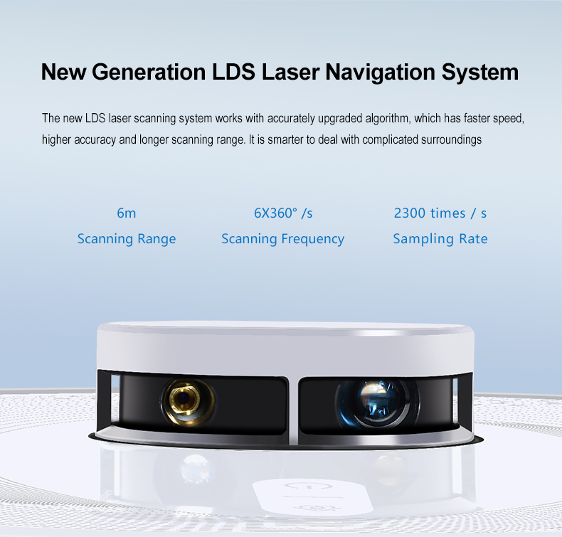
EX6 Laser radar Robot vacuum cleaner
Feature
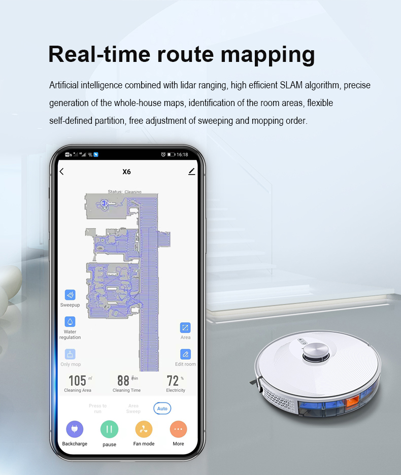
1. Lidar positioning and memory navigation, automatic map construction, and 10 maps can be stored
2. Automatic planning cleaning, fixed-point cleaning, wall cleaning and three-level suction adjustment
3. Make an appointment for cleaning, clean the designated area and set the restricted area
4. Nidec brushless DC motor fan, 3000pa high suction, 650ml dustbin
5. V-shaped floating anti winding medium sweep.
6,55db noise 2600mAH lithium battery working time within 120 minutes (5200mAh optional)
7. Electronic virtual wall, electronic area control
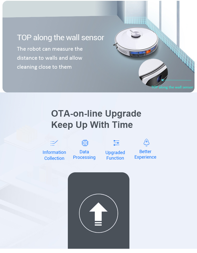
8. Graffiti app electronic map display, intelligent virtual restricted area, support OTA upgrade and tmall elf, Alexa and Google home voice assistant
9. Carpet pressurization, volume adjustment, 2cm obstacle crossing, voice prompt, top wall sensor
10350ml electric water tank mopping
11. Automatic charging + radar anti-collision + anti falling
12. IML high end cover
Japan, Germany, etc. use this unit as a unit representing the performance of the sweeper, but in other regions, the input power is directly misunderstood as a unit representing the performance of the sweeper.
After reading the introduction of this article, we already know what are the characteristics of the floor sweeping robot. This kind of thing can clean the house well, especially the sundries in some dead corners. Therefore, we can choose directly according to the characteristics. In addition, the above also tells you what the principle of the floor sweeping robot is, We should use it according to what we know.


Floor Vacuum Cleaner Robot,Household Appliances,Home Electrical Appliances
Shenzhen Ewong Technology CO.LTD , https://www.ewongteches.com