The adjustment of the flow rate in the fan system often uses a way of changing the opening of the baffle, thus generating additional pressure loss on the baffle and wasting a lot of energy. For example, in a thermal power plant, an air blower is provided for the combustion of boilers, and a suction blower for excluding high-temperature smoke generated by the boiler combustion is often used to ensure the negative pressure of the boiler hearth, the oxygen content of the flue gas, and the corresponding steam temperature and steam pressure due to frequent changes in the load of the boiler. Stable, need to adjust the delivery, suction volume and coal powder. The adjustment of the air volume is usually achieved by adjusting the population-oriented blades. The blade opening often varies between 60% and 80%. The throttling loss of this blade is 20% to 30% of the rated capacity of the fan [l, 2]. The use of variable frequency speed control technology to transform the fan system not only saves energy, but also makes the system run more reasonably reliable. This has become the consensus of the majority of engineering and technical personnel. However, how to determine the speed ratio of the wind turbine and run it in an efficient area to achieve optimal operation of the fan efficiency is still rare in the literature. For a single fan operation, the problem is simpler; when multiple fans are connected in parallel or in series, this is essentially a nonlinear programming problem.
This paper analyzes the operating conditions of the fan system, and classifies them into two types of systems based on the characteristics of the pipe network. The optimal control strategy is analyzed for a single fan operation, multiple parallel connections, and series operation to determine the optimal speed ratio [3]. Simulation experiments show that this method is effective. The new system has been put into operation in a thermal power plant in Shandong Province and has achieved good economic and social benefits.
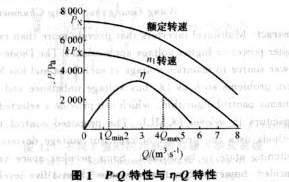
1 Fan operating conditions analysis 1.1 Fan characteristics PQ characteristics of the fan curve (ie, pressure - flow curve) can not be calculated by theoretical methods, but can only rely on experimental methods [3]. According to the experimental data, when the fan is running at the rated speed no, the P-Q characteristic can be fitted according to the following equation:
P=Px-SxQ2(1)
In the formula, Px and Sx are the fitting parameters.
It should be noted that the PQ curve with a hump does not conform to the above equation. This characteristic may cause the wind turbine to be in unstable operation, and surge may occur during parallel operation [1]. It should be avoided when selecting a fan. Therefore, this feature is not considered in this paper.
According to the fan's similarity theorem, the PQ curve moves down [4] when the rotation speed is down. If the rotation speed is reduced to n1, the P-Q characteristic becomes:
P=kPx—SxQ2(2)
In the formula: k=(n1/no)2, is the speed ratio.
According to η-Q characteristic curve, when Q is too high or too low, the efficiency η will drop sharply, so the flow range should be limited to [Qmin, Qmaxl is too low, η is also very low, it should also limit the speed range to [kmin, 1]. This will ensure that the fan operates in an efficient area, as shown in Figure 1.
When multiple fans are connected in parallel, the PQ characteristics in parallel can be obtained by adding the flow of each fan under the same pressure. When the series is working, the pressure of each fan under the same flow can be added together to obtain the series connection. PQ characteristics. The parallel and series characteristics equations of the two fans are:

1.2 Pipeline characteristics and system classification According to fluid mechanics, the pressure loss due to resistance friction when a wind passes through a pipeline can be expressed by the following type of pipe network characteristics:
R=PST+SQ2(5)
In the formula: R is the pipe network resistance; S is the pipe network resistance coefficient; PST is the working pressure requirement of the system, namely the pressure at the exit of the pipe network is higher than the pressure value of the fan outlet.
When the system is running steadily, the actual pressure and R balance provided by the fan, the intersection point of the P-Q curve and the pipe network characteristic curve is the stable working point of the fan.
The fan system can be roughly classified into two categories according to the PST: PST=0 in the first type system means that there is no special requirement on the working pressure, and the fan needs to provide the flow required by the system according to the load, for example, the boiler induced air and air supply system and the heating furnace The combustion air blower, mine ventilation system, etc.; the flow rate in Class 2 system cannot be directly controlled by the blower, mainly determined by the user's valve connected to the pipe network. The blower needs to ensure the most unfavorable user-end pressure in the pipe network, such as the gas transmission. system.
1.3 Energy Saving Principles For Type 1 systems, the flow rate is often adjusted by adjusting the baffle opening. This method essentially changes the characteristics of the pipe network to change the fan operating point, as shown in Figure 2.
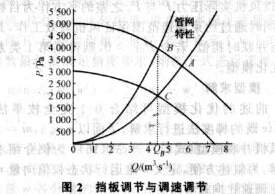
The original fan works at point A. If the flow is reduced to QB by adjusting the baffle, the fan will work at point B. It can be seen that the pressure generated by the fan not only does not decrease, but also increases, and the excess energy is wasted on the baffle. on. If the speed of the fan is adjusted and the PQ characteristic is changed so that the operating point moves to the point C along the pipe network characteristics, it can exactly meet the system requirements and greatly reduce the energy consumption.
For Type 2 systems, constant pressure regulation is often used. According to the flow rate QA under the most unfavorable conditions and the pressure PST required by the user, the pressure PA provided by the fan is determined, and the fan parameters are selected to operate at the point (PA, QA).
During the operation, only the pressure P at the outlet of the fan is detected, and the dispatch is performed according to P so that the water pressure is constant at the PA. If the flow rate is reduced from QA to QB, the fan operating point will move along the horizontal line P=PA to point C (PA, QB). However, according to equation (3), the pressure that should be provided at this time is PB:
PB=PST+SQB2(6)
Therefore, more PA-PB is provided. This part of the energy will be consumed in the pipe network, wasting energy.
If the scheduling is performed according to the flow rate Q and the user required pressure PST at the same time, the above problem can be solved. If the flow rate is reduced from QA to QB, according to equation (5) and the detected flow QB, the fan should provide PB at this time. After the dispatch, the wind turbine will work at the best operating point B (PB, QA) to exactly meet the needs of users.
It can be seen that in this scheduling process, the fan operating point moves along the characteristic curve of the pipe network, which always meets the user's demand and no energy is wasted. The energy-saving effect is the best, as shown in FIG. 3 .
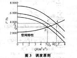
The so-called most energy-saving work point is to make the flow and pressure of the fan exactly meet the needs of the system, so that the working point moves along the characteristics of the pipe network, and the fan always runs on the intersection of the PQ curve and the original pipe network characteristic curve. Although the requirements of the two types of systems are different, there are many similarities in the speed control strategy. Although the PST of type 1 system is 0, in order to overcome the pipe network resistance R, the fan still needs to provide a certain pressure P=R. Therefore, the Category 1 system can be considered as a special case when the PST=0 of the Type 2 system. The following analysis of the optimization model is limited to Type 2 systems.
2 Optimization Problem Modeling 2.1 Single Fan Operation Assume that a fan characteristic parameter is PXi, SXi, ki, and the pipe network resistance coefficient is S. For Type 2 systems, if the pressure requirement is PST, Qe, the expected value of the flow, then R = PST + SQ2 (7)
k=[PST+(S+Sx)Qe2]/Px(8)
When PST = 0, the adjustment method of the type 1 system can be obtained. It can be seen that the single fan operation problem is relatively simple, and the analytical expression of the speed ratio can be obtained directly.
2.2 Parallel operation Assume that a system has n fans in parallel operation, in which the ith fan is the speed control fan, i = 1, 2, ..., m; mP = Pxi-SXiQ2i = m = 1, m = 2, ..., n(10)
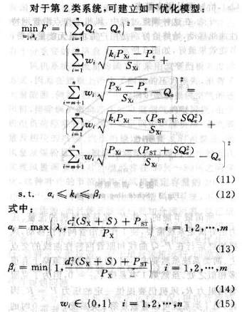
This model uses the square of the difference between the sum of the actual flow rate of each fan ∑Qi and Qe as an objective function, and at the same time, it ensures the efficient operation of the fan by restricting the range of speed regulation. Λi,ci,di in equations (13) and (14) indicate the speed range and flow range constraints kmin, Qmin, and Qmax when the fan is operating efficiently. By calculating Qmin, Qmax. The best operating point speed ratio is compared with λi,1, so that the constraints for efficient operation are only expressed by the speed range [αi,βi], which simplifies the model. Ωi indicates the working status of the ith fan (1 means work, 0 means not work). In the model (Equation (11) to Formula (15)), let PST=0, that is, an optimization model of the first type of system is obtained.
2.3 Series operation Fan characteristics and pipe network parameters are the same as equations (9) and (10) for parallel operation. The PQ characteristics of a series of n-stage fans are:

For Type 2 systems, if the system requires a working pressure of PST and Qe is the expected flow rate, the pressure Pe that should be provided is:
Pe=R=PST+SQe2(17)
In order to operate the fan at the best operating point, an optimization model is established as follows:
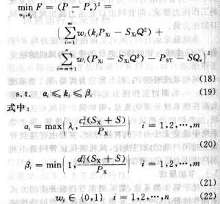
The λi, ci, di, ωi parameters of this model are the same as those of the parallel operation model. The objective function is the square of the difference between the actual pressure of the fan P and Pe. At the same time, the fan speed is guaranteed by the range of speed regulation, and the idea is similar to that in the parallel connection. If PST is set to 0, an optimization model for the first type of system is obtained.
2.4. Model Solving The aforementioned optimization model can be solved by combining 0-1 complete enumeration and Wolfe-reduced gradient methods. In the following, the multiple-fan parallel model (Eqs. (11)-(15)) is taken as an example to introduce the solution steps when n=5 and m=2. For narrative convenience, define the n-dimensional operating state weight vector w and the m-dimensional speed ratio vector k:
w=[w1,w2,w3,w4,w5](23)
k=[k1,k2](24)
Where: w is the running state vector of each fan; k is the speed ratio vector of each speed control fan.
The model solution steps are as follows:
a. 0-1 complete enumeration, which is the method to choose the optimal solution from all feasible solutions. When w is taken as a certain value, whether each fan is working is completely determined, and the objective function F only changes with the speed ratio of seven. All possible values ​​of w are shown in Table 1, a total of 31, except for the 7 combinations of only fixed-speed fans, actually 24 types.
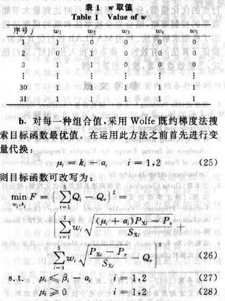
Then it is solved according to Wolfe's reduced gradient method.

c. Compare the optimal value of the objective function under each w, and select the "best" one as the output of the solution. The best here does not mean that the value of the objective function is the smallest, because in the engineering practice, blind pursuit of accuracy is meaningless. Considering that the large motor, especially the prime mover of the constant speed fan, is often difficult to start, it is better that the start-stop operation is better under the condition that the flow rate requirements are satisfied. If there are more than one w under the objective function of the optimal value to meet the accuracy requirements, the choice of the following formula:
Where: wj is the possible value of w in Table 1; j is the number of the value of w, j=1,2,...,31, and j≠4,8,12,16,20,24, 28;i is the serial number of each component of the vector w; ε is the accuracy requirement of the objective function; w' is the weight vector of the current running state; kj* is the best speed ratio vector when wj.
Equation (29) calculates the distance between two vectors according to the Hamming distance, and the value is equal to the number of unequal elements in the two vectors, that is, the number of start and stop. In this way, the optimal solution (w*, k*) with the least number of start-stop actions can be guaranteed as the solution result.
3 Simulation experiments Mathematical software MATLAB optimization toolbox is used for simulation calculation, taking n=5 and m=2 as examples. Fan parameters: speed control fan PXl = 30kPa, PX2 = 20kPa, SXl = 48Pa · m-3 · s, SX2: 20Pa · m-3 · s, kmin = 0.5; fixed speed fan Px = 25kPa, Sx = 30Pa·m-3·s. Pipeline resistance coefficient S = 100.
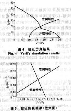
For the parallel model (Equations (11)-(15)), given (PST,Qe)=(10kPa, 18.86m3·s-1), the result of the operation is:
w*=(1,0,1,0,0),k*=(0.5821,0.80)
The best objective function value is:
F*<10-4
Since the constant speed fans have the same capacity, there are more than one set of solutions that meet the accuracy requirements. For example: w18=(1,0,0,1,0), k18=(0.5821,0.80), etc. Here, equations (29) and (30) should be used to select the solution with the least number of starts and stops (w*, k*) as the model. A graphical method can be used to verify the above results, namely to find the intersection of the PQ characteristic curve and the pipe network characteristic curve, as shown in Figure 4 and Figure 5. It can be seen that the accuracy of the algorithm is satisfactory.
w*=(1,0,1,0,0),k*=(0.5386,0.80) The objective value of the objective function is:
F*=5.4498X10⁻¹⁰<10-4≈0
In fact, when w12=(0,1,l,0,0), k12=(0.80,0.5056) or w26=(1,1,0,1,0), k26=(0.5386 , o.80), etc., The objective function value searched for by the gradient method also satisfies the 10-4 precision requirement. At this time, the solution with the least number of starts and stops is selected as the optimum according to equations (29) and (30). solution. Here suppose that when w*=(1,0,1,0,0), the number of start-stops is the least.
4 Application At present, most of the blowers and induced draft fans equipped with boilers in domestic thermal power plants are operated by one single unit or two parallel units. The capacity of a single unit is large. This configuration is relatively reasonable in the era of fixed speed transmission, but it is no longer reasonable today when the frequency conversion speed control technology is highly developed. The main reason is that: the capacity of the single machine is large, and when the load of the generator set is small, the no-load loss of the motor will be large, and the frequency converter equipped during the transformation is also large in capacity, the cost is high, and the control flexibility is poor. Of course, from the perspective of efficiency optimization, this scheme is more reasonable. Therefore, when the research team reformed the boiler fan system of a 125MW/200MW unit in a thermal power plant in Shandong Province, four 280kW and 380V fans were used in parallel.
The original system adopted the method of adjusting the population-oriented blades to adjust the amount of air to be sent and sucked to ensure the boiler furnace negative pressure, the amount of flue gas oxygen, and the corresponding steam temperature and steam pressure stability. This type of blade has a very large throttling loss. Adopting frequency conversion technology and optimizing the control strategy for efficiency not only completely eliminates the cut-off of the blades, but also ensures that the wind turbine operates in an efficient area with an average energy saving rate of 35.6% and a significant energy saving effect. The technological transformation investment can be recovered within 25 months.
5 Conclusion In this paper, a non-linear planning method is used to study the optimal operation control strategy for wind turbines. Aiming at the single operation and multiple serial and parallel operation conditions of the fan system, an optimization model was set up to optimize the system operation at the best operating point, and the control strategy to achieve the maximum energy saving effect during the speed regulation operation was analyzed, combined with the complete enumeration method and both The approximate gradient method proposes a model solving algorithm. Using MATLAB for simulation experiments, the effectiveness of the algorithm is verified. After the new system is put into use, the operation is stable, the energy-saving benefits are significant, and the promotion prospect is broad.
Our reverse osmosis membrane water treatment systems are designed to provide efficient and reliable water purification solutions for various applications. With our advanced technology, our RO membranes can effectively remove contaminants, such as dissolved salts, bacteria, and organic compounds, from water sources.
One of the key advantages of our RO membranes is their ability to achieve high water production rates and desalination rates under specific pressure conditions. This ensures that our systems can deliver a consistent supply of purified water, making them suitable for large-scale industrial and municipal water treatment systems. RO membranes feature a stronger membrane surface, which enhances their durability and longevity. This means that our membranes can withstand harsh operating conditions and maintain their performance over an extended period of time, reducing the need for frequent replacements and maintenance. RO membranes have excellent oxidation resistance, allowing them to effectively remove contaminants that may cause oxidation in the water. This ensures that the treated water meets the required quality standards and is safe for consumption or industrial use.
Moreover, our RO membranes operate using an extremely low-voltage working mode, which not only reduces energy consumption but also improves the overall system efficiency. This results in cost savings for our customers and contributes to a more sustainable and environmentally friendly water treatment process.
Ro Membrane, Ro Membrane Filter For Frp Membrane Housing, Reverse Osmosis Membrane, Brackish Water Membrane, Membrane Element
Hebei Chengda Water Technology Co.,Ltd. , https://www.arclionchengda.com