1. Reason for improvement
The traditional 12T forklift brake system mainly consists of air compressor 1, oil-water separator combination valve 2, gas storage tank 3, pressure switch 4, air brake valve 5, brake light switch 6, air booster pump 7, left clamp The disc brake 8, the right caliper disc brake 9 and the liquid storage tank 10 are composed as shown in FIG.

The power of the air compressor 1 is taken from the engine, and when the engine is running, the air compressor 1 is driven to rotate, so that the air compressor 1 outputs compressed air. The compressed air passes through the oil water separator combination valve 2 and enters the gas storage tank 3. When the pressure of the compressed air is greater than 0.75 MPa, the oil-water separator combination valve 2 is automatically deflated to maintain the pressure of the gas storage tank 3 within 0.75 MPa. The pressure switch 4 is used to detect the air pressure in the air tank 3. When the pressure reaches 0.75 MPa, the pressure switch 4 sends an electric signal, and the low air pressure alarm buzzer stops sounding, prompting the driver to drive.
When the driver steps on the air brake valve 5, the compressed air enters the air urging pump 7 cylinder from the air outlet of the air brake valve 5, and pushes the cylinder piston to the right to drive the brake fluid output in the hydraulic cylinder. The brake fluid supplies the left caliper disc brake 8 and the right caliper disc brake 9 through the pipe to generate a braking action. The air booster pump 7 cylinder piston area is much larger than the hydraulic cylinder piston area, and the pressure generated by it can increase the brake fluid pressure to 13 MPa. The liquid storage tank 10 is for replenishing the brake fluid for the hydraulic cylinder of the air booster pump 7.
The system mainly has the following two defects: First, there is only one air booster pump in the brake system. If the pump is suddenly damaged during operation, the whole vehicle will not be braked and has certain danger. Second, the brake fluid capacity of a single air booster pump is less. When the forklift is working for a long time, the brake fluid heats up rapidly, and even the brake fluid boils and overflows from the liquid storage tank 10. When the brake fluid is reduced, the braking performance will be degraded, which will affect the safety of the forklift.
2. improvement measures
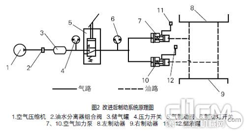
The improvement measures are to add one air booster pump and one oil storage tank to the brake system. After the improvement, there are two air booster pumps and two liquid storage tanks in the brake system, namely the air booster pumps 7, 10 and the liquid storage tanks 11, 12, as shown in FIG.

The discharge pipes of the two air booster pumps 7, 10 are respectively connected to the left brake 8 and the right brake 9, and act on the two brake cylinders of the left and right caliper brakes, respectively. Even if one air booster pump is damaged, the brake system can still act as a brake, thus improving the safety of the forklift brake.
In order to reduce the length of the brake pipe and make the brake more sensitive, the air booster pumps 7, 10 are mounted on the main beam of the forklift. The liquid storage tanks 11, 12 are installed in the cab and connected to the air booster pumps 7, 10 through long hoses, so that the driver can easily observe the liquid level in the liquid storage tank. Increasing the liquid storage tank can increase the brake fluid capacity and reduce the temperature rise of the brake fluid too fast.
The improved 12T forklift brake system has a shorter braking distance, more responsive and more reliable work.
Various kinds of industrial control cabinets for customers are customized, which are mainly divided into strong electric control cabinet, weak current control cabinet, all kinds of single machine control cabinets and all kinds of single machine control cabinets.
The strong electric control cabinet has modular combination electric cabinet, GGD control cabinet, PLC control cabinet and so on. The weak current control cabinet adopts special PVC material to make the process simulation screen, which can clearly and intuitively reflect the operation process and facilitate monitoring.
The user can choose the control mode combined with the central control of the analog screen and the computer control ingredients or the computer complete screen control mode.
Electronic Control,Electric Control System,Power And Control Systems,Control System
XinxiangHexie Feed Machienry Manufacturing Co.Ltd , http://www.hxfeedmill.com