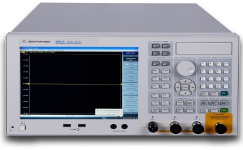
Introduction: Today, we should introduce in detail the test setup method of the E5071C network analyzer:

1. Frequency setting: Press Start on the instrument panel as the start frequency and Stop as the stop frequency. If we want to measure 2.4G to 5.8G, we first press Start to set it to 2.4G, then press Stop to set it to 5.8G.
2. Transmission and reflection test function setting: After opening Meas in the instrument panel, the display menu will have S11 S21 S12 S22 (S11 S22 is reflection and S21 S12 is transmission) Note: VSWR and return loss are in the reflectance test. , That is to say tested in S11 or S22, S11 and S21 are the first test port test, and S22 and S12 are the second port test.
3. VSWR and Insertion Loss Test Settings: After the panel selection button Format is opened, there are several indicators of the test products in the display menu. We can choose according to the test indicators needed by our products, such as the more commonly used SWR (standing wave Ratio), Log mag (insertion loss)
4. Multi-window and multiple test line settings: After the panel select button Display is opened, there will be many functions in the display menu. We use the Num of Traces to set to 2, and two test lines will appear in the display. One is yellow and the other is blue, but now both test lines are in a test window. We can also separate the two test lines in two test windows for testing; we can display the selection window in Allocate. .
5. Change two test settings: Use the Trace key on the panel to switch between the yellow and blue line settings.
For example: to see the display Tr1 S11 yellow line settings, select on the panel, Format inside select SWR (Stop wave ratio test) At this time the yellow line is to test the VSWR, we press the Trace button to set the blue line test Tr2 S21 Prev Press Format selection Log mag (insertion loss test) At this point we can now measure the VSWR and insertion loss of our product at the same time.
6. Instrument calibration method: select the Cal display inside the panel keys; Calibrate press 2-Port Cal in the next step; Next enter into the corresponding calibration after the reflection, such as Open (Short) Short circuit) Load PORT1 port and PORT2 port to confirm the end of school, if the end of school display will be ticked; next press and then press the screen menu to return the next step by Transmission next step on the test line to put PORT1 and a PORT2 two ports connected; the next press Thru; the next step to press Return: the next step by Isolation; PORT1 port and PORT2 two (optional) connection disconnected; the next step by Port1-2Isol; the next step by the Return; Press Done in one step; calibration is complete! At this point, connect PORT1 and PORT2, the yellow line should be at the bottom of the display, the blue line should be in the middle, turn the cursor on and test out the indicator yellow line should be about 1.020, the blue line indicator should be -0.0005 or so.
7. Cursor opening method: After selecting the button Marker on the panel, the display screen will have multiple choices from 01-08. We can select one or more test cursors to read our product indicators.
Mini concrete mixer can be used to mix dry hard concrete, plastic concrete, flow concrete, light aggregate concrete and various mortars, so they were popular in precast concrete plants, industrial and civil construction works, bridges, water works, roads, airport and harbors. JS series mini Concrete Mixers are double horizontal axle forced mixers with two advantages of independent performance or forming simple concrete mixing plants with PLD series of batching machines.
Mini Concrete Mixer Machine,Small Concrete Mixer Machine,Self Loading Concrete Mixer,Home Built Concrete Mixer
Shandong Zeyu Heavy Industry Science and Technology Co.,Ltd. , https://www.sdjsseriesconcretemixer.com