10 years of experience in electricians and cattle, summary of 41 cases of wiring methods (previous post)
01
Motor wiring
Generally used in three-phase AC motor terminal frame leads to six terminals, when the motor nameplate marked with Y-shaped connection, D6, D4, D5 connected, D1 ~ D3 power supply; for the delta connection method, D6 Connected to D1, D4 is connected to D2, D5 is connected to D3, and then D1 to D3 are connected to the power supply. See Figure 1 for the connection method connections.
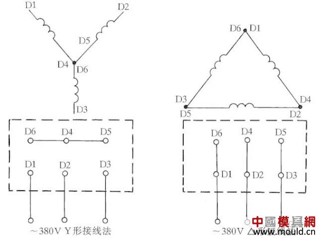
Figure 1 Three-phase AC motor Y-shaped and â–³-shaped wiring method
02
Three-phase blower wiring
Some three-phase hair dryers have six terminal blocks, and the wiring method is shown in Figure 2. The â–³-connected method should be used to connect a 220V three-phase AC power supply, and the Y-connected method should be connected to a 380V three-phase AC power supply. General 3 inch, 3.5 inch, 4 inch, 4.5 inch models according to this method. Other hair dryers should be connected according to the connection marked on the nameplate.
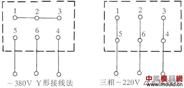
Figure 2 Three-phase hair dryer six outlet terminal wiring method
03
Single-phase capacitor running motor wiring
Single-phase motor wiring method is many, if not according to the requirements of wiring, there will be the possibility of burning the motor. Therefore, when wiring, be sure to see the wiring method stated on the nameplate.
Figure 247 shows the wiring method for the IDD5032 single-phase capacitor-operated motor. Its power is 60W, and the capacitor uses a voltage of 500V and a capacity of 4μF. Figure 3(a) shows the forward connection and Figure 3(b) shows the reverse connection.

Figure 3 IDD5032 single-phase capacitor running motor wiring method
04
Single-phase capacitor running motor wiring
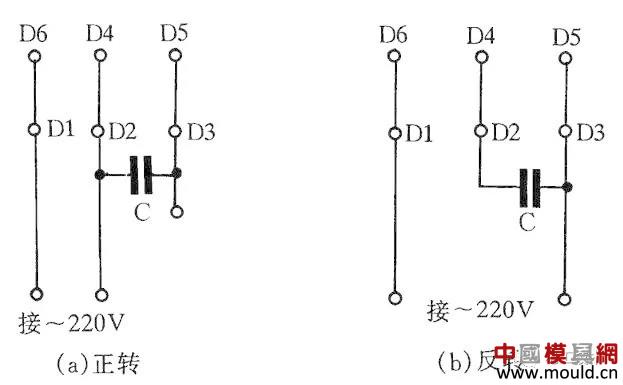
Figure 4 JX07A-4 single-phase capacitor running motor wiring method
Figure 4 is a JX07A-4 type single-phase capacitance running motor wiring method. The motor power is 60W, with a 220V/50Hz AC power supply and a current of 0.5A. Its speed is 1400 rpm. Capacitors are 400V to 500V with a capacity of 8μF. Figure 4(a) shows the forward connection and Figure 4(b) shows the reverse connection.
05
Single-phase blower wiring
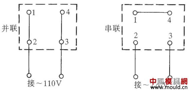
Figure 5 Single Terminal Blower Four Lead Terminal Connections
Some single-phase blowers lead out four terminal blocks. The wiring method is shown in Figure 5. The connection and connection method shall be used to connect the 110V AC power supply, and the series connection method shall be used to access the 220V AC power supply.
06
Y100LY series motor wiring
At present, Y series motors are widely used. Y series motors have the advantages of small size, beautiful appearance and energy saving. It has two wiring modes: one is a delta shape, and its connection terminal W2 is connected to U1, U2 is connected to V1, V2 is connected to W1, and then it is connected to a power supply; the other is a Y-shaped terminal W2, U2, V2 is connected and the remaining three terminals U1, V1, W1 are connected to the power supply. See Figure 6 for wiring.
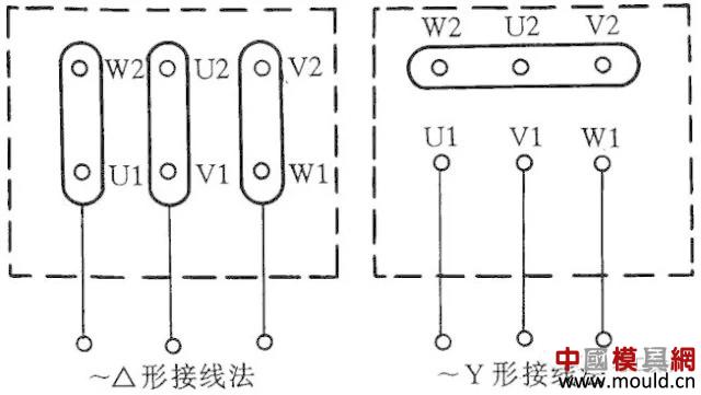
Figure 6 Y100LY series motor connection method
07
Low voltage transformer short circuit protection circuit
At present, the work lights and running lights of the machine tools are all provided with low-voltage transformers to provide 36V safe voltage. Because the lamps often move during use, they are prone to short-circuit faults, causing fuses to blow or even destroy the transformer. If you use a 36V small relay or 36V AC contactor to make the transformer on/off switch, you can avoid burning the transformer. The circuit is shown in Figure 7.

Figure 7 Low-voltage transformer short circuit protection circuit
Working principle: After closing S, press the button SB1, the transformer will output 36V low voltage to make the relay or AC contactor KA pull. After the button SB1 is released, the KA self-locking contact keeps the KA closed and continues to apply power to the transformer. If a secondary fault occurs in the secondary of the transformer, the voltage of the relay coil is zero. At this time, KA will lose power and release the transformer power supply, so the protection transformer will not be destroyed.
08
Two-speed motor 2Y/2Y wiring method
Fig. 8 shows the lead wire connection method of the 2Y/2Y motor double speed stator wire set.
The connection according to Fig. 8(a) is a rotational speed, which is connected according to Fig. 8(b) to obtain another rotational speed.
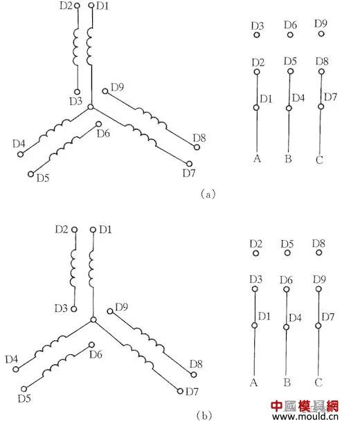
Figure 8 Two-speed motor 2Y/2Y wiring method
09
DC electromagnet rapid demagnetization circuit
After a DC magnet has been powered off, there is sometimes a negative result due to the presence of residual magnetism. Therefore, we must try to eliminate remanence. In FIG. 9, YA is a DC magnet coil, and KM is a contactor that controls YA start-stop. When the KM is closed, the YA is energized. When the KM is reset, the YA is disconnected from the DC and demagnetized rapidly.
The working principle of fast demagnetization is that after the DC solenoid is de-energized, the AC power supply charges the capacitor C through the bridge rectifier and YA. As the voltage across the capacitor C increases, the charging current decreases and the current through the YA increases. Again alternating, so that the electromagnet quickly demagnetize. The capacity of the capacitor C is determined by field tests based on the actual situation of the electromagnet. R is the discharge resistance.
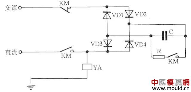
Figure 9 DC magnet fast demagnetization circuit
10
Prevent the brake solenoid from delaying the release of the line
A three-phase asynchronous motor braked by an AC solenoid is sometimes delayed by the brake electromagnet, causing brake failure. The reason for the delayed release of the electromagnet is that although the main circuit power supply of the contactor is cut off, the residual magnetism of the motor exists, and the stator winding generates an induced electromotive force to be added to the ac electromagnet so that the electromagnet will not be released immediately. The solution is very simple, as long as in the AC solenoid coil in series with a AC contactor normally open contact, so that disconnect the motor power at the same time disconnect the electromagnet and motor winding coil, you can immediately release the electromagnet. See Figure 10 for the circuit.
YA in the circuit is the brake electromagnet. After the power is turned on, the brake is released. After the power is turned off, the YA brakes immediately.
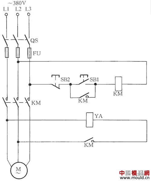
Figure 10 Preventing delayed release of the brake solenoid
11
Self-excitation DC motor demagnetization protection circuit
If the excitation DC circuit of the excitation motor is disconnected, it will cause the motor to overspeed and cause serious adverse effects. Therefore, it is necessary to perform demagnetization protection.
In the excitation circuit, an undercurrent relay KI is connected in series, and its normally open contact is connected to the control circuit. When the excitation current disappears or decreases to the set value, KI is released, and the KI normally open contact opens, cutting off the armature power supply of the motor and stopping the motor, thus avoiding the overspeed phenomenon. See Figure 11.
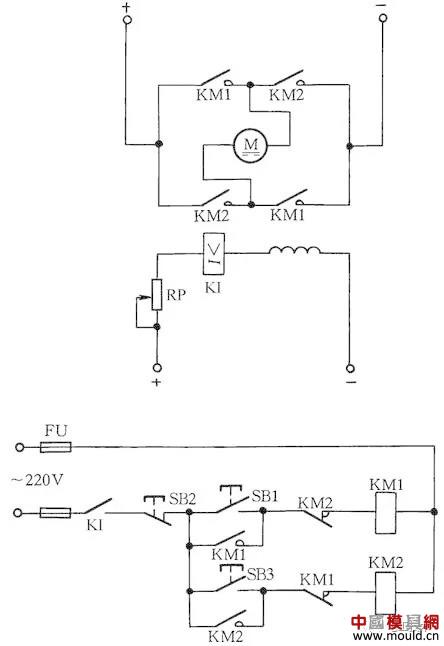
Figure 11 Excitation DC motor loss protection circuit
12
AC Contactor Emergency Wiring Without Auxiliary Contact
When the auxiliary contactor of the AC contactor is damaged and cannot be repaired and is in urgent need of use, the wiring method shown in Fig. 12 can be used to meet emergency use requirements. Press SB1, AC contactor KM pulls. After the button SB1 is released, the contact of the KM doubles as a self-locking contact, so that the contactor is self-locking, so that the KM is still held in and pulled. In the figure, SB2 is the stop button. When it is stopped, the time to press SB2 is longer. Otherwise, after the hand releases the button, the contactor pulls in again, allowing the motor to continue running. This is because the power supply voltage is cut off, but due to the effect of inertia, the rotor of the motor still rotates, and the stator winding will generate an induced electromotive force. Once the stop button is quickly reset, the induced electromotive force is directly applied to the coil of the contactor, causing it to pull again. The motor continues to operate. When the contactor coil voltage is 380V, it can be connected as shown in Figure 12 (a); when the contactor coil voltage is 220V, it can be connected as shown in Figure 12 (b). The wiring of Fig. 12(a) is also defective in that when the motor is stopped, its lead wires and motor are charged, making maintenance less safe. Therefore, this kind of circuit can only be used in emergency, and when the motor is being repaired, the total power switch QS controlling the motor should be disconnected. This should be paid special attention.
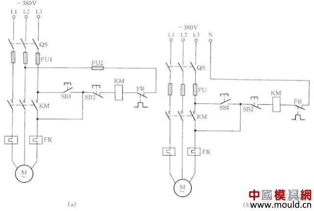
Figure 12 AC contactor emergency wiring missing auxiliary contacts
13
Encrypted motor control circuit
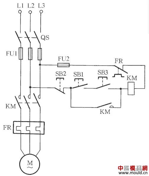
Figure 13 Encrypted motor control circuit
To prevent accidental operation of electrical equipment and to prevent non-operators from activating certain equipment switch buttons, encrypted motor control circuits can be used, as shown in Figure 13. When operating, first press the SB1 button, after confirmation, then press the encryption button SB3 at the same time, so that the control circuit can be turned on, the KM coil can be pulled, and the motor M can rotate. Instead of the operator who does not know the encryption button (the encryption button is installed in a hidden place), the device switch cannot be operated.
14
AC contactor low voltage start line
When the supply voltage is less than 85% of the rated voltage of the AC contactor attraction coil, the starter contact armature will jump more than it can and it cannot be reliably pulled in. A rectifier tube is connected in series in the control loop of the AC contactor and it is changed to DC start AC operation. , you can avoid the above problem. The AC contactor low voltage start circuit is shown in Figure 14. Pressing the button SB1, the DC voltage half-wave rectified by the diode VD is applied to the coil of the AC contactor KM and the KM is pulled. Its auxiliary contact shorts the diode VD and AC contactor is put into AC operation.
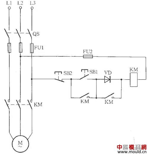
Figure 14 AC Contactor Low Voltage Startup Circuit
Because of the large starting current, this line is only suitable for occasions where the operation is infrequent. In the circuit, VD should use a diode with a withstand voltage greater than 700V, and the current should be determined according to the AC contactor coil current.
15
HF-4-81 series generator control circuit
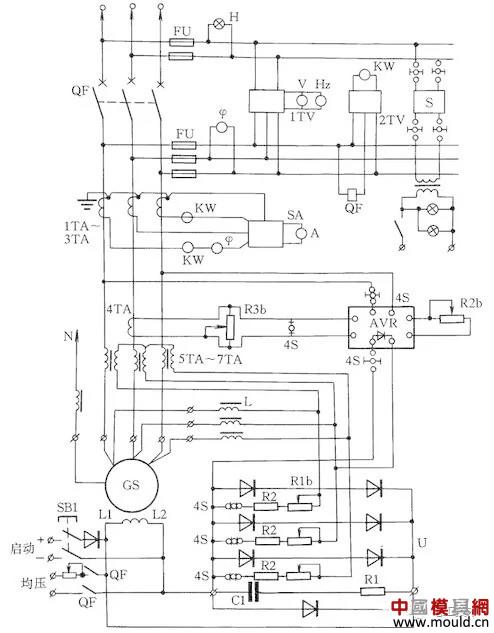
Figure 15 HF-4-81 series generator control circuit
The HF-4-81 series generator control circuit is shown in Figure 15. It is matched with the T2XV series small three-phase synchronous generator. Synchronous generator excitation system uses electric compound phase compound excitation and pressure regulation. The generator terminal voltage is phase-shifted by the linear reactor L, and then it is combined with the secondary voltage of the current transformer 5TA~7TA in the generator load circuit. After being rectified by the three-phase bridge rectifier, the generator GS excitation is automatically adjusted.
16
Single-phase capacitive motor circuit
The single-phase capacitor motor has a large starting torque, a small starting current, and a high power factor, and is widely used in household appliances such as electric fans and washing machines. In order to facilitate the maintenance and installation, the commonly used wiring method of this motor is introduced.
Figure 16(a) shows the reversible control circuit. Switch S2 can be used to change the direction of the motor. This circuit is generally used in household washing machines.
Figure 16 (b) is the wiring with auxiliary winding, toggle switch S, can change the tap of the auxiliary winding, that is to change the actual withstand voltage of the main winding, thus changing the speed of the motor, this wiring method is often used on the electric fan.
Figure 16 (c) is the wiring circuit of the capacitor motor with the speed regulation of the reactor. Because the reactor winding (which plays a depressurizing role in the circuit) is in series, adjusting the input amount of the reactor winding can change the rotation speed. This method is currently widely used in home electric fan circuits. When starting the motor, it is usually first dialed to "1" block, which is a high block. At this time, the reactor is not connected to the line, so that the motor starts at full pressure, and then dial "2" or any block to adjust the motor speed .
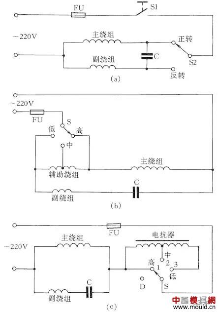
Figure 16 Single-phase capacitive motor circuit
17
Concrete mixer line
Cone JZ350 mixer circuit shown in Figure 17, the working principle is when the cement, sand, stones with good material, the operator press the button 2SBF, 2KMF contactor coils have electric pull, so that the material hoist motor 2M forward, the hopper feed lift. When it rises to a certain height, the baffle stopper collides with the limit switches 1SQ and 2SQ, causing 2KMF to be de-energized. At this point, the hopper has been raised to a predetermined position, the material is automatically poured into the mixer, and the rise is automatically stopped. At this point when the operator presses the down button 2SBR, the winch system drives the hopper down and waits until the material port is flush with the ground. The stop gate collides with the limit switch 3SQ, causing the 2KMR contactor to power off and release, automatically stopping the descent. The next time the material is ready, the mixer material is ready, the operator presses the 3SB1 again, and the 3KM contactor is pulled in and out, so that the water supply pump motor 3M operates, supplying water to the mixer, and at the same time, the time relay KT got electricity work, until the water supply is proportional to the raw material (the water supply time is determined by the KT time relay adjustment, according to the raw material and water ratio determination), KT action delay end, so that 3KM automatic release, the water supply stops. Add water to complete the stirring. Press the 1SBF forward rotation button, 1KMF will pull on electricity, 1M rotates forward and stir, and press the 1SB stop button after mixing to stop. When the material is discharged, press the 1SBR button, and 1M reverses to automatically mix the concrete slurry. Then press 1SB, the contactor 1KMR power off release, 1M stalled, the discharge stopped.
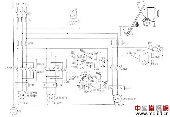
Figure 17 concrete mixer line
18
Self-made practical insulation detector
Figure 18 shows a self-made insulated detector circuit that can be used as both a line insulation monitor and a megohmmeter to check the insulation resistance of motors and testers. When the isolating switch QS is closed, the leakage current between the entire winding and the grounded shell flows through the insulating layer and the resistors R1, R2 under the action of the phase voltage. If the insulation resistance is in line with the standard (namely insulation resistance value is greater than 0.5MΩ), the leakage current is very small, the voltage drop at R2 is less than the ignition voltage of the helium bubble, Ne does not light; when any two or three phase at the same time on the chassis When the insulation resistance is reduced, the leakage current is greatly increased and the neon bubble Ne is ignited so that the insulation can be judged as unacceptable.
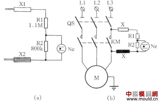
Figure 18 Self-made practical insulation detector
19
Three-phase asynchronous motor changed to single-phase operation
If only a single-phase power supply and a three-phase asynchronous motor are used, the three-phase asynchronous motor can be changed to single-phase operation by using a shunt capacitor.
As shown in Figure 19: Figure (a) is a Y-connected motor connection method, Figure (b) is a delta connection motor connection method. In order to increase the starting torque, the starting capacitor CQ is connected to the line at startup and exits after starting.
Calculating Formula of Working Capacitance CG Capacity
CG=1950I/Ucosφ(μF)
Where: I is the motor rated current; U is the single-phase supply voltage; cosφ is the power factor of the motor. When the working capacitance is calculated, the starting capacitor uses 1~4 times of the working capacitance.
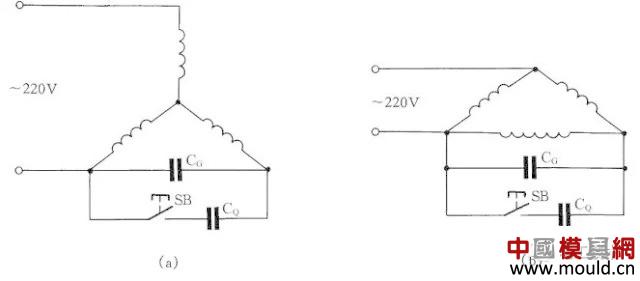
Figure 19 Three-phase asynchronous motor changed to single-phase operation
20
Thermal Relay Calibration Table
Thermal relays are prone to thermal aging during long-term power cycling, which changes their operating characteristics. One of the most important measures to maintain the consistency and stability of the characteristics is to regularly check the thermal relay.
Thermal relay calibration table shown in Figure 20, which is mainly composed of voltage regulator TV, step-down transformer T, potentiometer RP, 410 millisecond meter and other components.
The three-phase bimetal (heat relay FR) should be connected in series to access the test circuit. Before calibration, check whether the scale current of the thermal relay matches the rated current of the motor. Then pass the current of 1.05 IN (rated current, adjusted by RP) to the thermal relay to check its synchronism, ie whether the three-phase bimetals are in contact at the same time. If it is not synchronized, use a flat-nose pliers to clamp the bimetal and bracket spot welding to adjust the synchronization.
After synchronicity is adjusted, start the test first, and apply 6IN current to the thermal relay FR. It should not act within 5s. Secondly, run the test and apply 1.05IN to the FR to heat the thermal relay to a stable hot state. After 30 minutes, slowly adjust the RP, make the FR action, and then turn it a little to make the FR contact open. Then increase the test current to 1.2 IN. At this time, the FR should operate within 20 minutes. In this way, the setting verification of the thermal relay ends.
Adjust the calibration should pay attention to the following two points: 1 is not allowed to use pliers to bend the bimetal, so as not to affect the stability of the protection; 2 check the connection conductor should have enough cross-sectional area, so as not to affect the operation time.
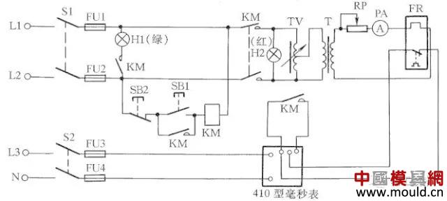
Figure 20 Thermal Relay Calibration Table
The article is unfinished, please continue to pay attention to "electrician cattle people 10 years of experience, summed up 41 cases of wiring methods (second part)"
DIN2632 PN6 Welding Neck Flange
Name: DIN2632 PN10 Welding neck flange
Size: DN10-DN3000
Material: A105 SS400 RST37.2 Q235 etc.
Manufacture process: Forged
Packing: Pallets plywood cases or according your requirement
Certification: ISO9001--2000.
v id="StyleTableProd">
Name
welded neck flange
Size
1/2" -200" (DN15-DN5000)
Wall thickness
150LB/300LB/600LB/1500LB/3000LB/6000LB
Standard
ASTM ANSI DIN JIS GB JB HG
Material
A234-WPB. A420-WPL6. A234-WP12. A234-WP11. A234-WP5.
Packaging
Wooden Cases or wooden pallet or as per customers requirement
Applications range
Petroleum, chemical, power, gas, metallurgy, shipbuilding, construction, etc
Min Order Quantity
According to customer' s requirement
Delivery Time
7-15 days or negotiable
Quality
First grade
Productivity
1, 2, 000T/Y
Others
1Special design available according to requirement
2anti-corrosion and high-temperature resistant with black painting
3All the production process are made under the ISO9001: 2000 strictly.
Keywords
WN flange, flange, Welding Neck Flange
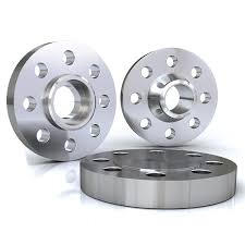
DIN 2632 Pn10 Welding Neck Flange
DIN 2632 Pn10 Welding Neck Flange, DIN 2632 Flange, DIN Pn10 Flange
Hebei Jimeng Highstrength Flange-tubes Group Co.,Ltd. , https://www.jimengflange.com